2. Hardware connection
This document introduces how to connect the board of BL70x series MCU.
2.1. BL706_IOT
2.1.1. Use CK-Link to Programming and debug
Connect the CK-Link USB interface to the PC with a suitable USB data cable
Connect the standard
JTAGpin of theHD3group of the Iot board with theJTAGpin ofCK-Linkusing a DuPont cableIf you do not use CK-Link to power the board, you need to power the board separately
bl706-iot board         CK-Link
-------------------------------
    JTAG_TDI     <-->     TDI
    JTAG_TDO     <-->     TDO
    JTAG_TCK     <-->     TCK
    JTAG_TMS     <-->     TMS
    VDD33        <-->     VREF
    GND          <-->     GND
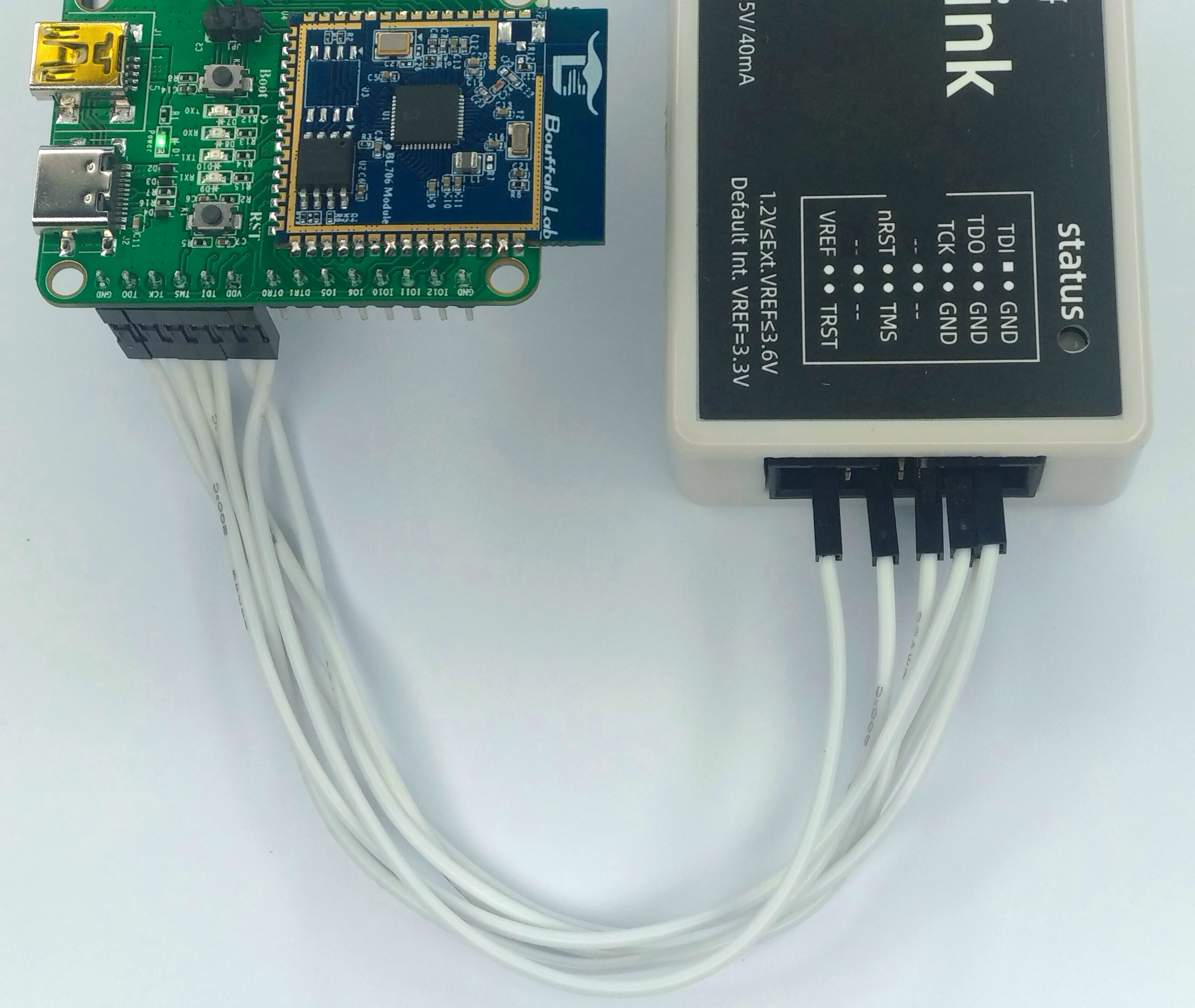
ck_link connect bl706-iot board
2.1.2. Use J-Link to Programming and debug
Connect the USB interface of j-link to the PC with a USB data cable
Connect the standard
JTAGpins of theHD3group of the Iot board with theJTAGpins of thej-linkusing DuPont wiresIn the case of j-link connection, the board needs to be independently powered, and the power supply of the board is connected to the
VTrefpin of j-link
bl706-iot board          j-link
-------------------------------
    JTAG_TDI     <-->     TDI
    JTAG_TDO     <-->     TDO
    JTAG_TCK     <-->     TCK
    JTAG_TMS     <-->     TMS
    VDD33        <-->     VTref
    GND          <-->     GND
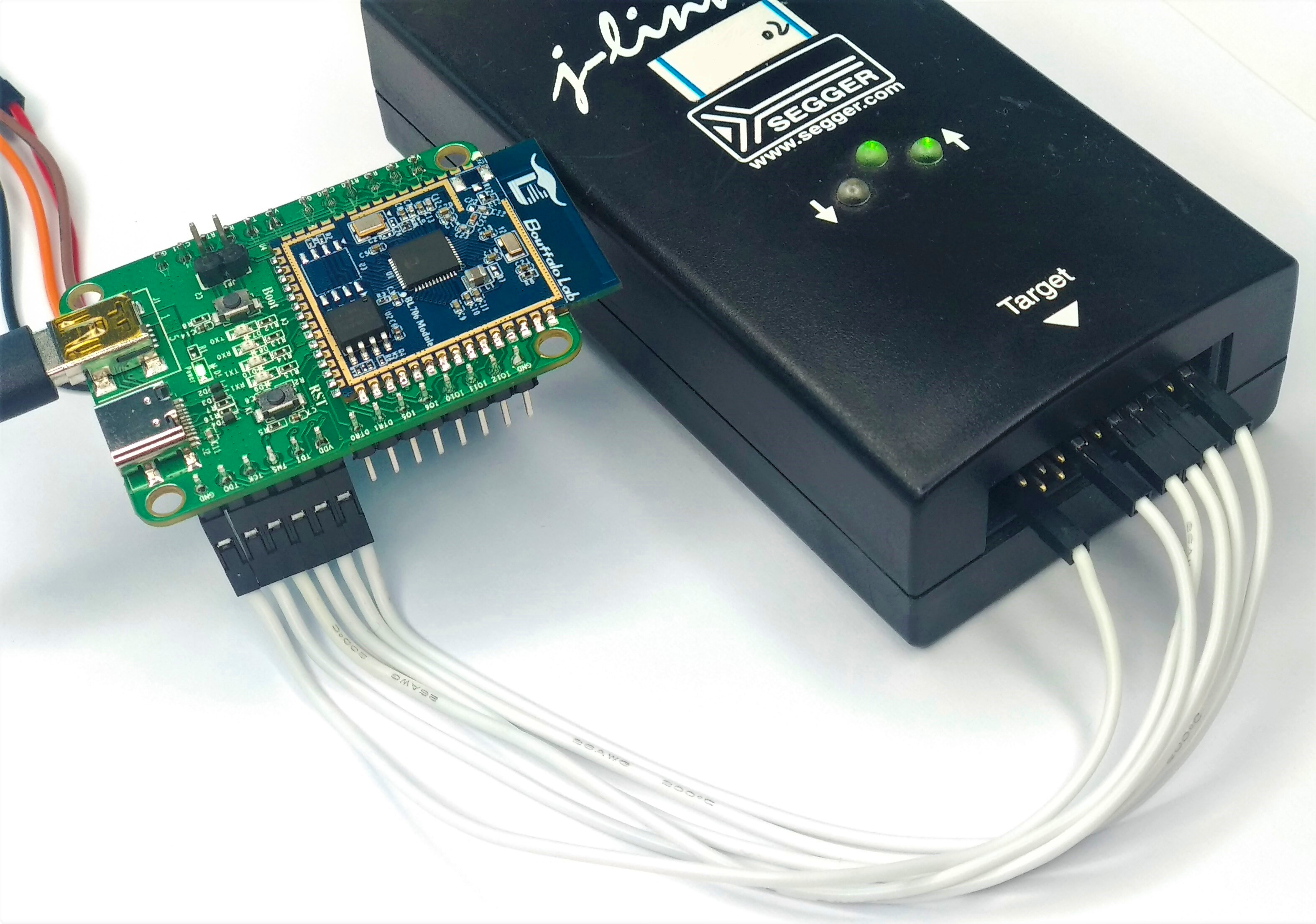
jlink connect bl706-iot board
2.1.3. Use serial port to Programming
Before using the serial port to Programming, please make sure that
Bouffalo Lab Dev Cubeor the command programming tool is installed correctlyUse
Type-C USBdata cable orMini USBdata cable to connect to theType-Cinterface orMiniinterface on the board.Press the
Bootkey on the board, don’t release it.Press the
RSTkey on the board, now you have enteredBoot ROM, you can release the two keys.At this time, you can see the corresponding serial port
COMnumber from theBouffalo Lab Dev Cube, if it does not appear, please click theRefreshkey to refresh.
If you don’t have a suitable data cable, you can also use some common
USB-TTLmodules to connect to the UART0 port of the development board for programming.UART0is on theHD1group, the connection method is as follows:
USB-TTL      BL702_IoT
----------------------
  3V3   <-->   VDD
  TXD   <-->   RX0
  RXD   <-->   TX0
  GND   <-->   GND
The programming step is the same as above
2.2. BL706_AVB
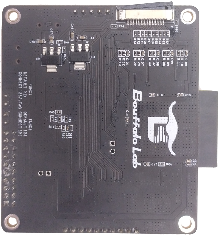
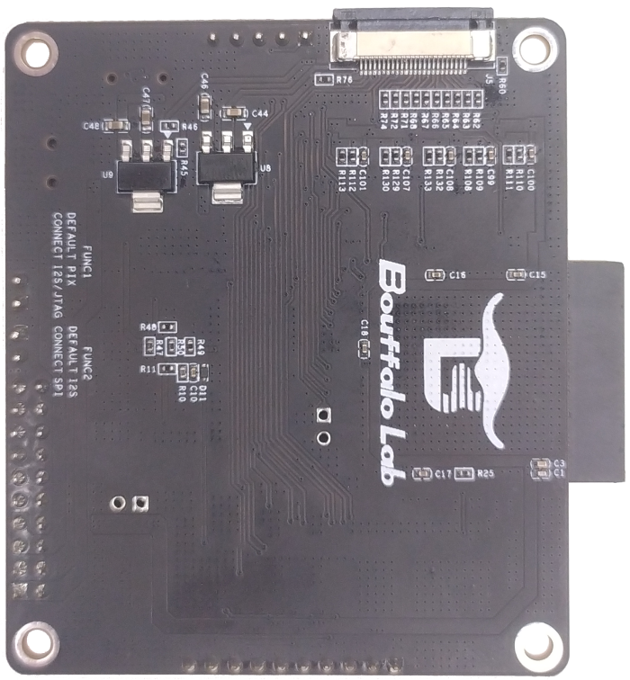
重要
BL706_AVB has multiple multiplexed pins, please check carefully whether the required function pins are multiplexed; FUNC1: “Default: PIX; Connect: I2S/JTAG”, FUNC2: “Default: I2S; Connect: SPI” ; If you need to debug, please remember to connect the FUNC1 jumper
2.2.1. Use Sipeed RV-Debugger Plus to programming and debug
Powering the BL706_AVB
Connect the RV-Debugger Plus debugger to the USB port of the computer. If the driver is not installed correctly, please refer to Sipeed RV-Debugger Plus driver installation settings, set the driver, and proceed to the following steps
Connect the debugger and the BL706_AVB with a cable (as shown in the figure below)
重要
The FUNC1 jumper must be connected when debugging, otherwise the pins will be multiplexed with other functions and the JTAG function cannot be used; the serial port function can be used normally
RV-Debugger connect bl706_avb board
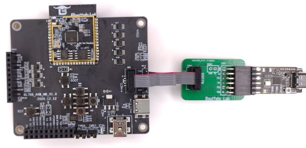
2.2.2. Use CK-Link to programming and debug
Connect the CK-Link USB interface to the PC with a suitable USB data cable
Connect the FUNC1 jump caps of the bl706_avb
Connect the pins of the
HD8group to the adapter board using a flat cableConnect the
JTAGpin of the adapter board with the correspondingJTAGpin ofCK-Linkusing a Dupont wireIf you do not use CK-Link to power the board, you need to power the board separately
bl706-avb board         CK-Link
-------------------------------
    JTAG_TDI     <-->     TDI
    JTAG_TDO     <-->     TDO
    JTAG_TCK     <-->     TCK
    JTAG_TMS     <-->     TMS
    VDD33        <-->     VREF
    GND          <-->     GND
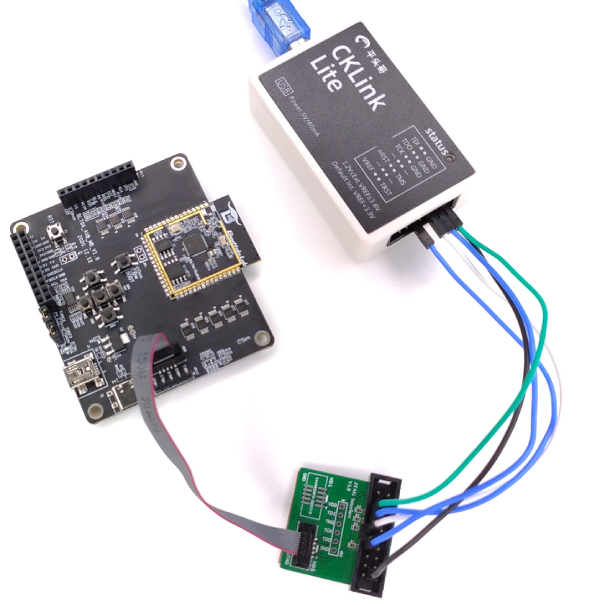
ck_link connect bl706_avb board
2.2.3. Use serial port to programming
Before using the serial port to programming, please make sure that
Bouffalo Lab Dev Cubeor the command programming tool is installed correctlyUse the
Type-C USBorMini USBdata cable to connect to the correspondingType-Cport orMiniport on the board.Press the
Bootkey on the board, don’t release it.Press the
RSTkey on the board, now you have enteredBoot ROM, you can release the two keys.At this time, you can see the corresponding serial port
COMnumber from theBouffalo Lab Dev Cube, if it does not appear, please click theRefreshbutton to refresh.
If you don’t have a suitable data cable, you can also use some common
USB-TTLmodules to connect to the UART0 port of the development board for programming.UART0on theHD12group, the connection method is as follows:If you use Sipeed RV-Debugger Plus to connect BL706_AVB through a flat cable, you can also use the serial port of Sipeed RV Debugger Plus
USB-TTL      BL706_AVB
----------------------
  TXD   <-->   RX0
  RXD   <-->   TX0
  GND   <-->   GND
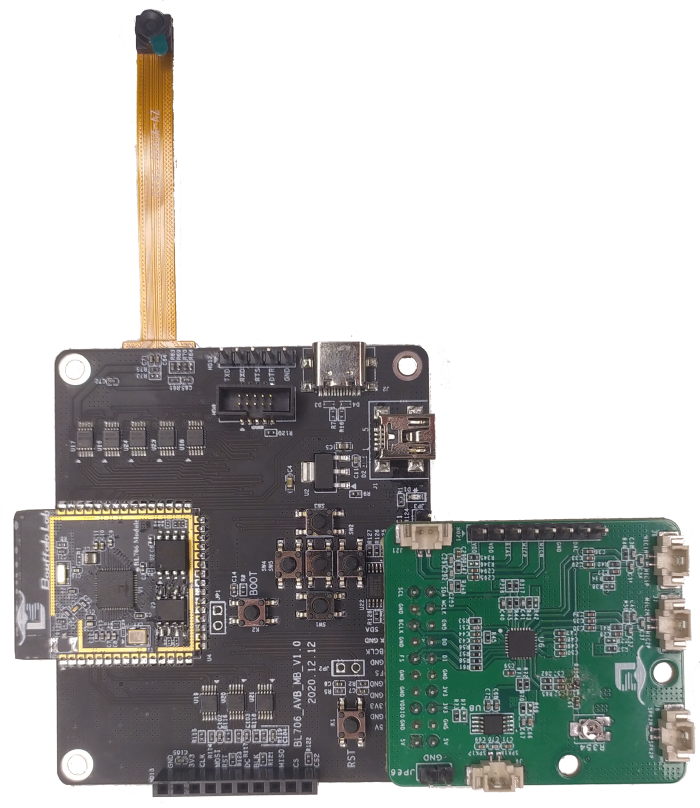
2.2.4. Connect BL706 AVB sub-modules
This section describes how to connect the BL706_AVB board with other modules, mainly including camera connection, Audio Codec module connection, and SPI screen connection.
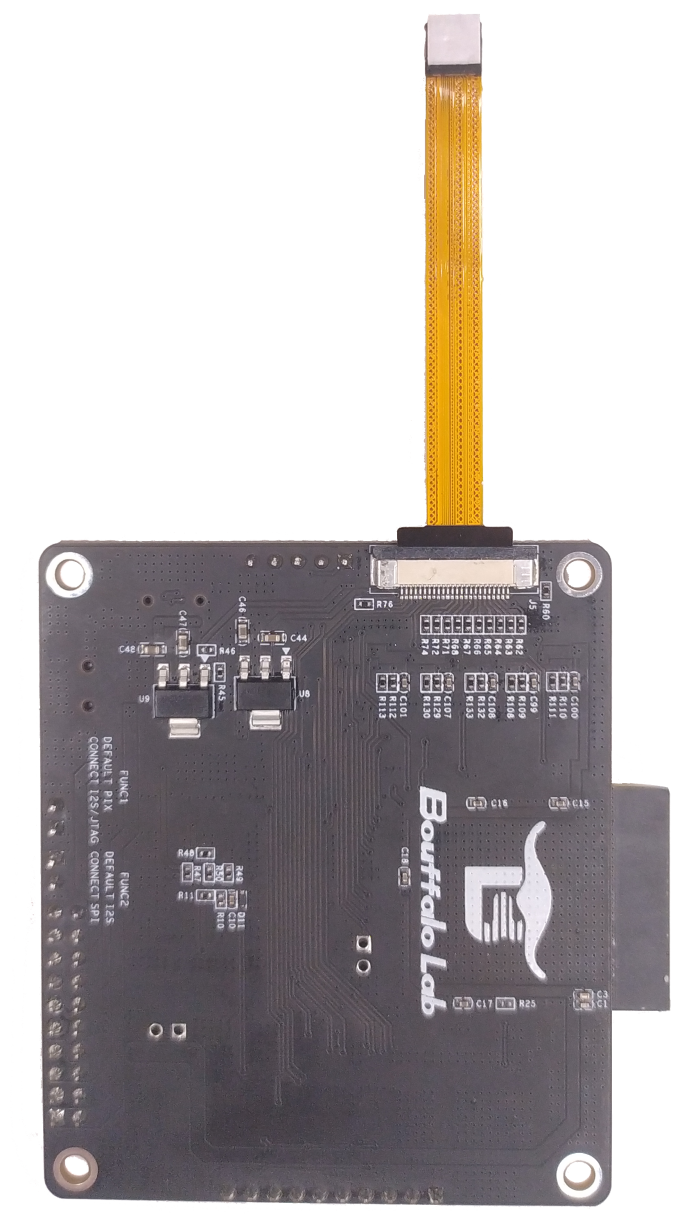
BL706_AVB Connects to GC0308 Camera Module
First, take the black locking part of the
J5drawer type FPC cable holder on the back of the BL706_AVB development board and pull it out from the edge
When fully disconnected, as shown in the figure below.
The FPC cable holder is a drawer down type, so next insert the camera with the side without metal contact points facing upwards into the FPC cable holder
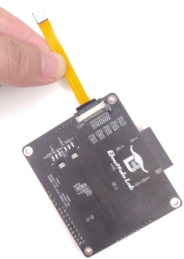
After inserting the camera, press the black latch tightly
BL706_AVB Connecting Audio Codec Modules
Insert the
HD19group of pins of Audio Codec module into theHD11row female socket of BL706_AVB development board; note that the module is extended outward.The schematic diagram is as follows: