7. Board Configuration System User Guide
In order to implement the idea of everything is a file, we propose a Board configuration system for embedded applications with different hardware configuration requirements. The Board configuration system is mainly used for initializing the three basic elements of clock, GPIO, and peripheral default configuration in embedded applications.
Board Configuration System contains three configuration files, and a bl_config_wizard graphical configuration software
clock_config.h Clock configuration Include file
peripheral_config.h Peripheral configuration Include file
pinmux_config.h Pin Function Configuration Include file
bl_config_wizard The graphical interface configures the above three types of files
The user only needs to modify three configuration files and the system will be initialized automatically, thus eliminating the need to call a series of complex and lengthy initialization functions in the user program. Boufflao Lab provides bl_config_wizard configuration software for users to quickly and easily generate configuration files for their projects.
bl_config_wizard supports PC-side online configuration, but currently does not support mobile terminal online configuration.
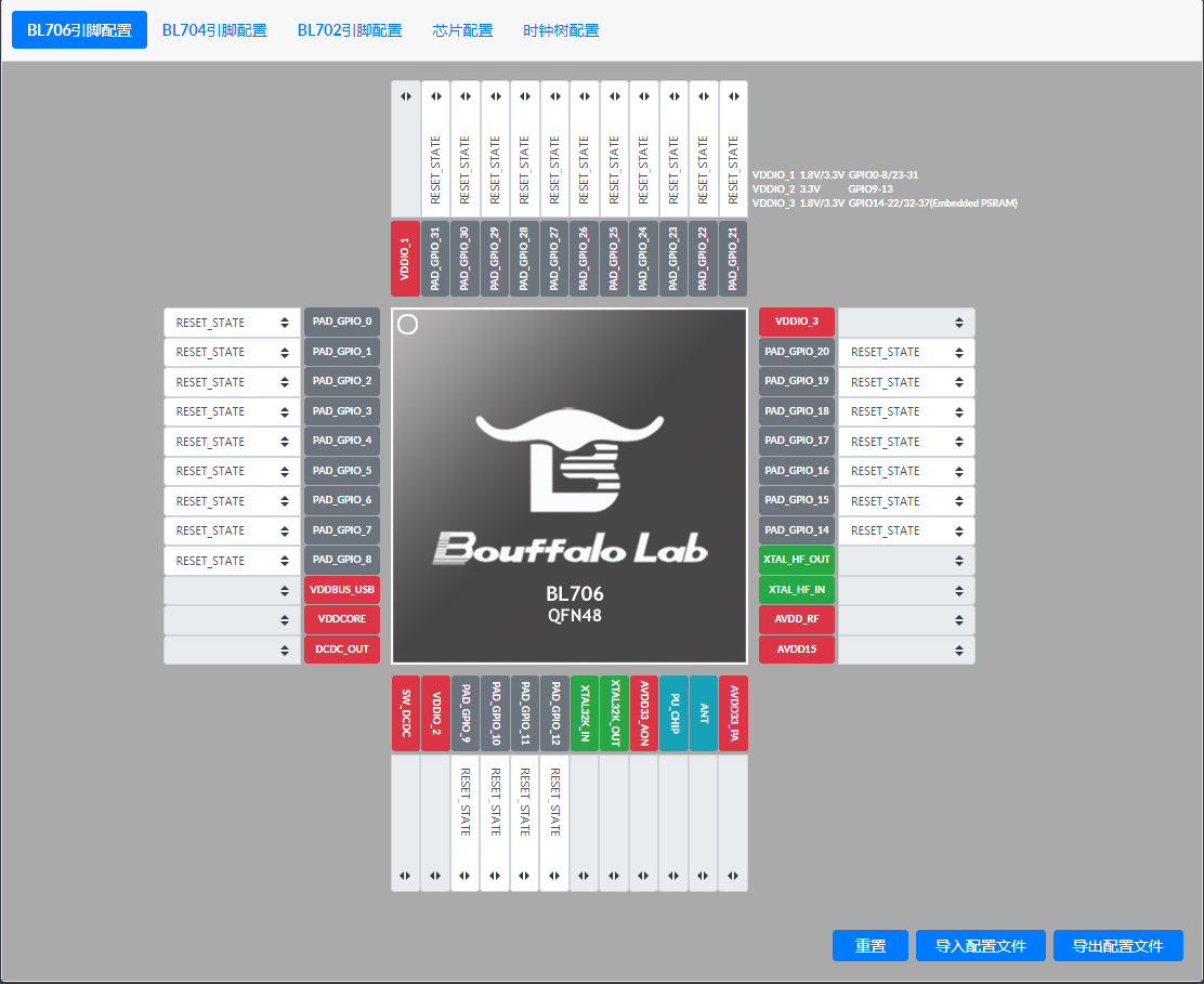
bl_config_wizard Preview
7.1. The features of each file in the Board configuration system
The board system is mainly used for different boards, different boards create different board files and put them in bsp/board directory, and a board file, in the case of pins not conflicting, can be shared to different demos, no need to create multiple projects and reduce the project file size.
错误
If there is a pin conflict and you have to use the same Board file, please modify the pins yourself
7.1.1. board.c
board.c Main initialization of clock and pins
7.1.2. blxxx_config.h
blxxx_config.h Mainly contains some header files for the HAL layer driver.
提示
The above two files do not need to be changed by the user, and the same MCU can be copied and pasted directly into your own board directory for use
7.1.3. clock_config.h
clock_config.h Mainly configures the clock sources for the system and peripherals as well as the frequency division system.
7.1.4. peripheral_config.h
peripheral_config.h It mainly contains the enablement of peripherals and the configuration of parameters.
警告
Macros starting with #define BSP_USING_XXX are used to enable the configuration of the peripheral, if the macro is not enabled, all functions of the peripheral cannot be used
警告
Macro starting with XXX_CONFIG, used to initialize the configuration of the peripheral, which is later used by calling device_open
7.1.5. pinmux_config.h
pinmux_config.h Mainly configures the GPIO pin function of the peripheral.
警告
In mcu sdk, all demos share this file, so some demos are not usable and require frequent changes to the pin function configuration in this file. If the user has already set the pin assignments, there is no need to modify them frequently.
7.2. Use of the Board configuration tool bl_config_wizard
The
bl_config_wizardcan be accessed by clicking on this link https://dev.bouffalolab.com/media/config/index.html wizard in the online version. Chrome, Firefox, Microsoft Edge browsers are recommended.
7.2.1. Generate a new pinmux_config.h file
Select
Pin & Peripheral Configurationin the window bar.Select MCU model, currently supports
BL706 pin configuration,BL704 pin configuration,BL702 pin configuration.Select the function of the pin, take
BL706 pin configurationas an example, click on the drop-down box of PAD_GPIO_XX and select the desired function, as shown in the figure.
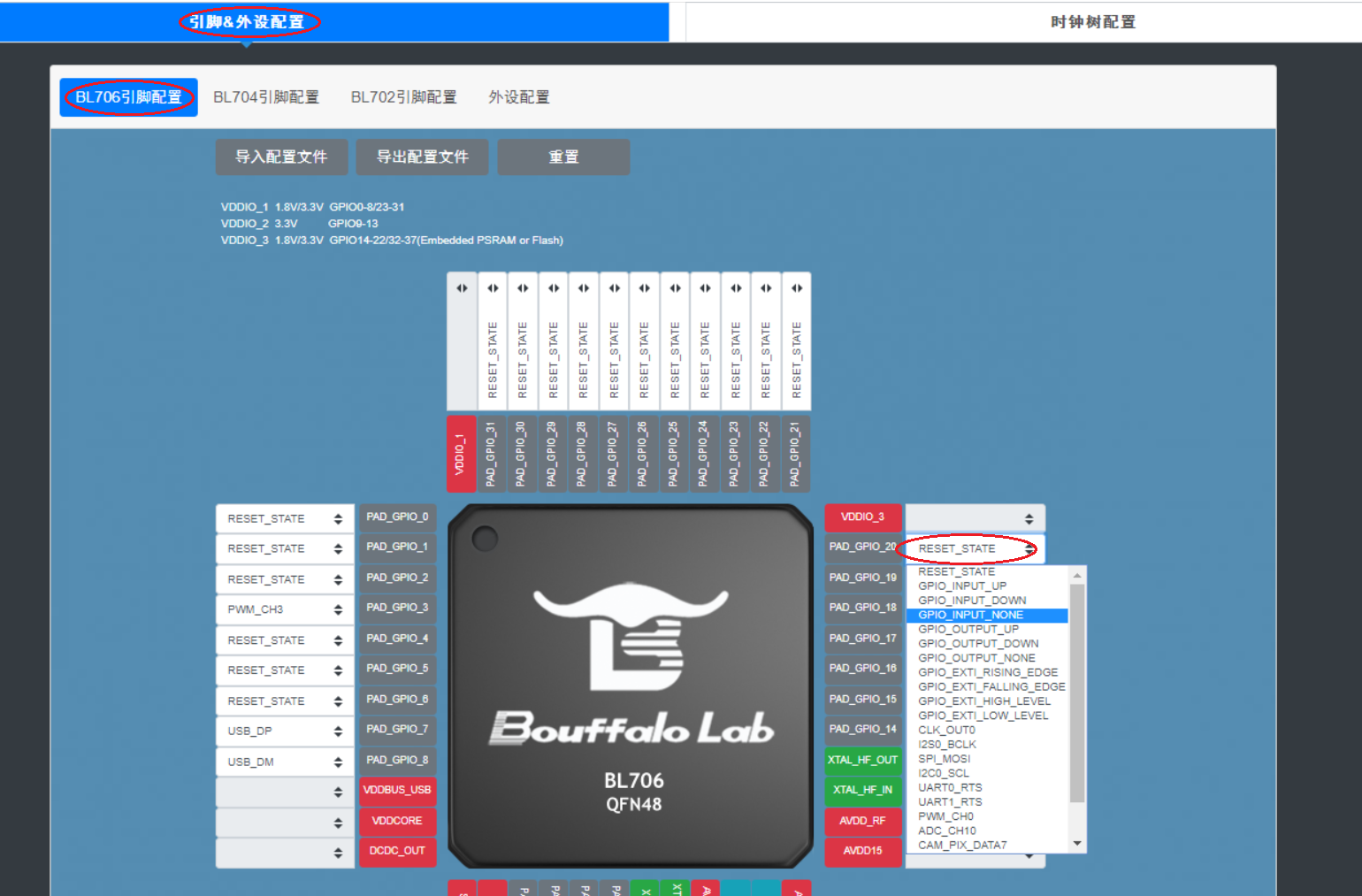
Select pin function
After configuring all the pin functions, click
Export Configuration Fileand then you can select the path and modify the file name in the pop-up box, as shown in the figure.
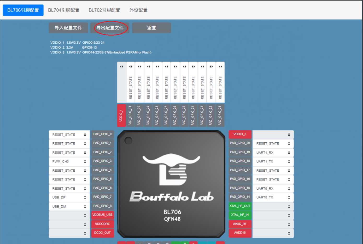
Exporting configuration files
7.2.2. Modify the original pinmux_config.h file
Often in use, instead of generating a new pinmux_config.h file, we make changes to the original pinmux_config.h file, and bl_config_wizard supports such a need.
Select
Pin & Peripheral Configurationin the window bar.Select MCU model, currently supports
BL706 pin configuration,BL704 pin configuration,BL702 pin configuration.Click on
import configuration fileand select the pinmux_config.h file in the pop-up box.Select the pin to be modified and click on its drop-down box to change the pin function
When you are done, click
Export Profileand then you can select the path and modify the file name in the pop-up box.
7.2.3. Modify the pinmux_config.h file in the CDK tool
pinmux_config.h Also supports the use of graphical configuration wizards in the CDK for adjusting the corresponding pin functions
Drag the pinmux_config.h file directly into the CDK text editor interface, and you will see the
Configuration Wizardtab at the bottom of the text editor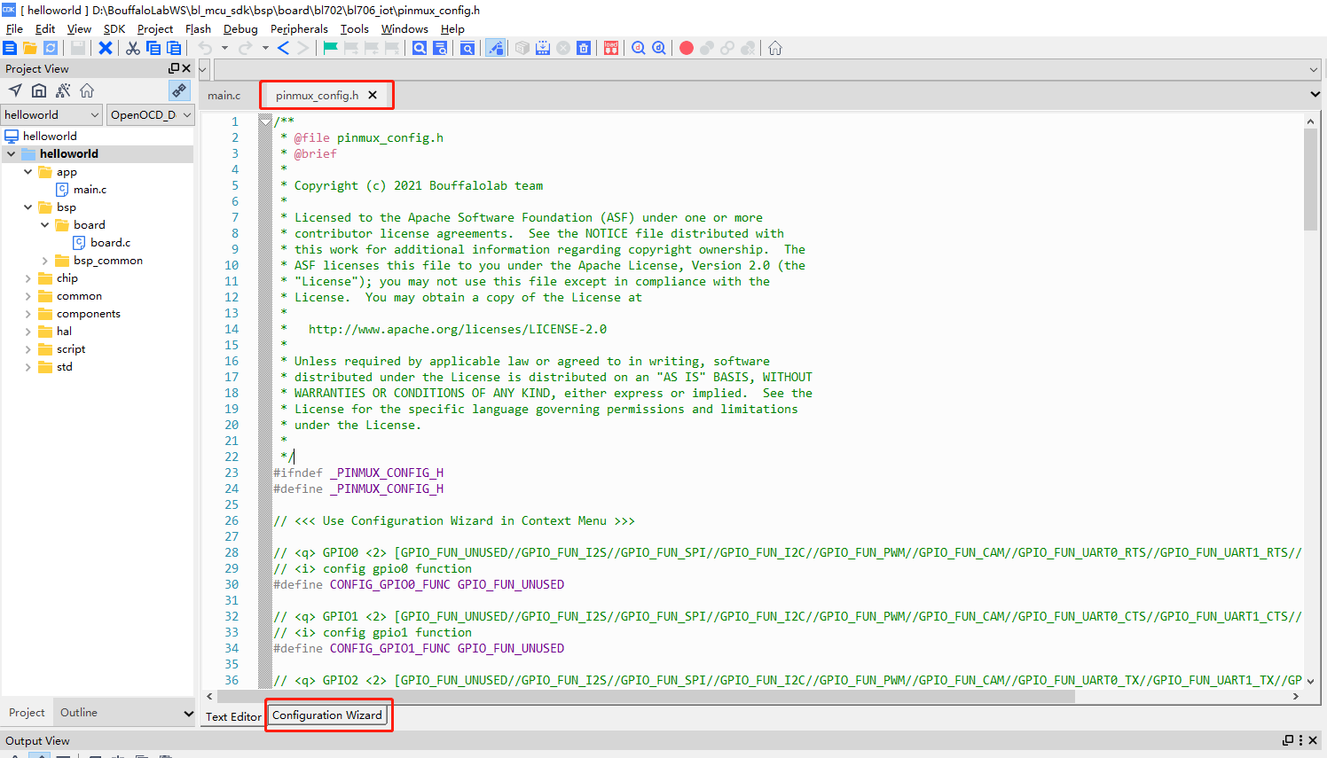
Configuration Wizard
Click on the
Configuration Wizardtab to open the graphical configuration wizard interfaceThe functions supported by the pin can be selected by selecting the drop-down box
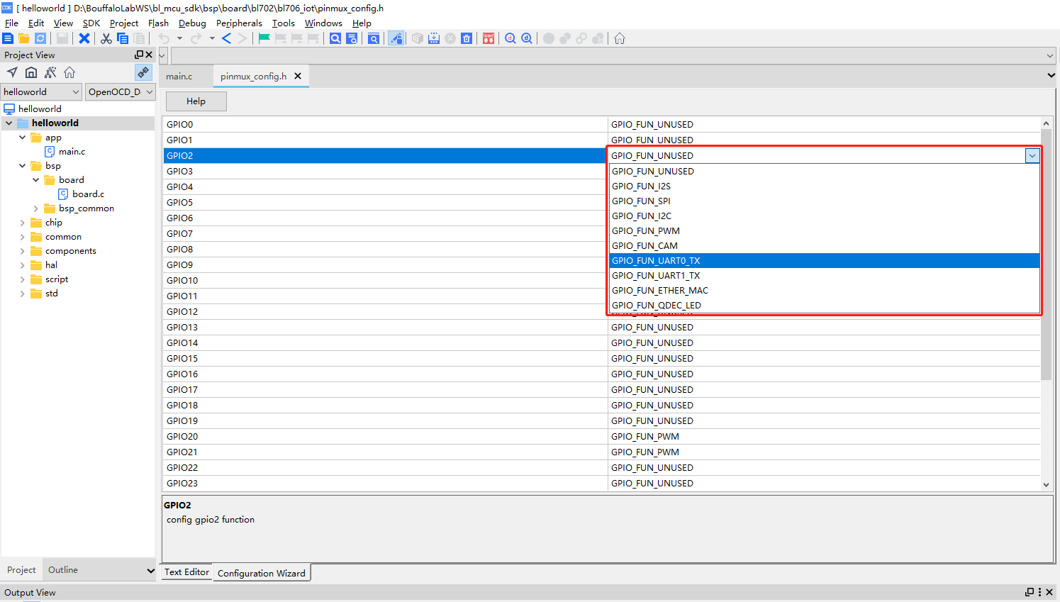
Graphical configuration wizard to set pin functions
Please refer to the Graphical Configuration Wizard section of CDK Help for more information on the specific functions and code rules of the Graphical Configuration Wizard.
7.3. Differences with STM32CUBEMX Configuration Tool
STM32CUBEMX is also a tool to configure the clock, peripherals and GPIO initialization, eventually generating a complete project with initialization at the very beginning of main.c, and the GPIO and peripheral initialization base will be called in stm32xxx_hal_msp.c.
/* MCU Configuration--------------------------------------------------------*/

/* Reset of all peripherals, Initializes the Flash interface and the Systick. */
HAL_Init();

/* USER CODE BEGIN Init */

/* USER CODE END Init */

/* Configure the system clock */
SystemClock_Config();

/* USER CODE BEGIN SysInit */

/* USER CODE END SysInit */

/* Initialize all configured peripherals */
MX_GPIO_Init();
MX_USART1_UART_Init();
MX_QUADSPI_Init();
void HAL_UART_MspInit(UART_HandleTypeDef* huart)
{
    GPIO_InitTypeDef GPIO_InitStruct = {0};
    if(huart->Instance==UART5)
    {
    /* USER CODE BEGIN UART5_MspInit 0 */

    /* USER CODE END UART5_MspInit 0 */
        /* Peripheral clock enable */
        __HAL_RCC_UART5_CLK_ENABLE();

        __HAL_RCC_GPIOB_CLK_ENABLE();
        /**UART5 GPIO Configuration
        PB12     ------> UART5_RX
        PB13     ------> UART5_TX
        */
        GPIO_InitStruct.Pin = GPIO_PIN_12|GPIO_PIN_13;
        GPIO_InitStruct.Mode = GPIO_MODE_AF_PP;
        GPIO_InitStruct.Pull = GPIO_NOPULL;
        GPIO_InitStruct.Speed = GPIO_SPEED_FREQ_LOW;
        GPIO_InitStruct.Alternate = GPIO_AF14_UART5;
        HAL_GPIO_Init(GPIOB, &GPIO_InitStruct);

        /* UART5 interrupt Init */
        HAL_NVIC_SetPriority(UART5_IRQn, 0, 0);
        HAL_NVIC_EnableIRQ(UART5_IRQn);
    /* USER CODE BEGIN UART5_MspInit 1 */

    /* USER CODE END UART5_MspInit 1 */
    }

}
提示
The projects generated by stm32 all work for one project and cannot be compiled for more than one project at the same time. If you use more than one project, you have to generate more than one of these two files. When using multiple projects, it will indirectly increase the file size and add duplicate files.